| University | Universities and Colleges Admissions Service (UCAS) |
|---|---|
| Subject | Mechanical Engineering |
Exercise 1:
Question 1
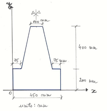
For the compound cross-section shown in Figure 1a, determine the position of the Centroidwith respect to the origin of the coordinate system shown in Figure 1a.
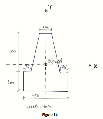
Q2 For the compound cross-section shown in Figure 1b, calculate the Second
Moment of Area of this cross-section about its horizontal axis X-X passing through the Centroid (xC, yC) determined in Q1 above.
Exercise 2:
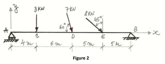
Q3 Calculate the reactions at supports for the simply supported beam subjected to the system of point forces shown in Figure 2.
Exercise 3:
Q4 For the simply supported beam shown in Figure 3, calculate the reactions at supports.
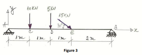
Q5 For the simply supported beam shown in Figure 3, calculate the Axial Force (N) in the beam at the sections A, C, D, E, and B shown in this figure.
Q6 Plot the Axial Force (N) diagram by using the results obtained in Q5 above.
Q7 For the simply supported beam shown in Figure 3, calculate the Shear Force (V) in the beam at the sections A, C, D, E, and B shown in this figure.
Q8 Plot the Shear Force (V) diagram by using the results obtained in Q7 above.
Q9 For the simply supported beam shown in Figure 3, calculate the Bending Moment (M) in the beam at the sections A, C, D, E, and B shown in this figure.
Q10 Plot the Bending Moment (M) diagram by using the results obtained in Q9 above.
Buy Answer of This Assessment & Raise Your Grades
Pursue Excellence with Engineering Assignment Help, at Diploma Assignment Help UK, unlock your full potential in mechanical engineering with our top-notch online assignment help services. Gain an edge in your university journey with expert guidance and achieve outstanding results. Trust our reliable solutions tailored to your academic needs, provided by experienced professionals. Take the leap toward success with us today!